Building a custom MIDI controller part 2 - Case Design
I should point out that this build was afforded to me by the company I work for, who sponsored it in time, equipment use and design software. Please check out what they do by going to www.ktassemblies.co.uk if this post is of any interest to you.
Conception
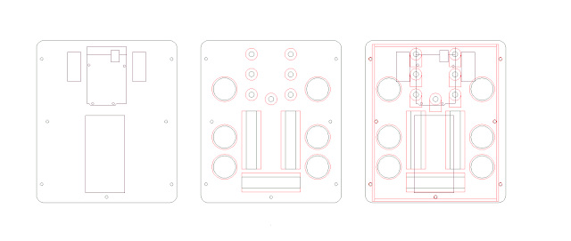
The first thing that I decided was that the controls should be mounted on some kind of board, which could be suspended over a box containing the main circuit - in this case consisting of the Arduino and two multiplexer boards. Ideally I wanted a custom box, but as I don't have access to anything like a 3D printer my options were to craft something another way, or buy a prefabbed project box from somewhere like RS components. Such boxes are usually very dull and often grey or beige, and rarely the most economic spatially - they are either far too large, or impractically small. Resorting then to creating my own enclosure I looked at which tools I had available and started to consider how to work with them. With a desktop laser cutter and a CNC router at my disposal the obvious material options were wooden board (either ply or MDF) and acrylic sheet. I settled on ply for the top and bottom parts of the enclosure as this could be worked with the CNC router to provide accurate mounting holes, as well as precision recesses for the button and slider fixings used to mount the sliders. Draftsight, which has a free version, provided a means to quickly sketch out a layout as well as make sure all the components fitted comfortably together with minimal wasted space.
I overlaid the top and bottom plates to ensure there was enough room for all the components.
Ply wood has a nice grain pattern so, in combination with some wood stain, I felt it would also look nicer than MDF. Being wood it also had the advantage that I could easily screw components to it, such as the sliders or circuit boards.
It was then only a matter of exporting the dxf to the routing software, then cutting the ply on the CNC machine.
To fix the top and bottom together I decided long M4 bolts could be used with some 5mm diameter brass tubing cut to length to act as spacers. I hoped the wood and brass combination would help give it an interesting and slightly retro look. The bolt and spacer method would also work to hold the sides in place by placing them either side of the acrylic sheet I planned to use, weaving the plastic between the spacers. Plastic nut covers on the end of the bolts also doubled as great feet!
The sides I decided would look good cut from gloss black acrylic sheet, 3mm thick. I could use the laser cutter for this, creating a finger joint cut for the corners, and bond it with acrylic adhesive. I also took this opportunity to cut a pattern in the sides which made it look a bit more interesting, as well as revealing some of the insides to anyone inspecting closely. It was at this point I made a mistake - and managed to glue one of the joints to the workbench! It came away after some teasing but left a rather unfortunate mark.
Rather than remake the sides, I opted for some brass angle which I placed on the corner:
Although I'm still undecided whether or not I prefer it.
Assembly.
With the parts cut and stained it was time to set about first mounting the controls on the top panel, before wiring them together. The previous post explains how the wires are connected so I won't reiterate - but as I added more wires and everything started to come together another problem was becoming apparent...
I had failed to take into account just how much space the wires were going to take up inside the enclosure. To be honest I'm still not entirely sure how I would have done so during the design stage - but I briefly worried that I was going to have to remake the sides after all, as well as re-cut the brass tubing to make the entire build deeper. Fortunately everything just about fitted, but it's certainly worth noting for any future projects...
Finishing touches.
With everything together the only remaining piece was the top of the panel, which looked pretty rough with the fader mounting plates exposed. This was remedied with a laser engraved plastic laminate, which I chose in black to match the sides. Not only did it give a smooth finish it provided the opportunity to mark on some labels as well as some basic graphic design. I probably could have added a bit more detail here, perhaps some patterning to match the sides - but as the laminate is removable I can (and may well) replace it with something a bit fancier.
So now it had the looks, it had the wires, and it had the electronics. It was time to actually test the controller, which I cover in the next post here.
Project repository on Github


Comments
Post a Comment