Building a custom MIDI controller part 3 - Tweaks and refinements
In this final post about my custom MIDI controller (the first two posts can be found here and here) I'm going to cover what happened when I tested the unit for the first time, the problems I uncovered, and how I worked around them.
At this point the project wasn't fully assembled, although it was all connected. Experience has taught me to expect a few kinks, and I anticipated the need for a few tweaks to the software. Fortunately I only encountered a couple of problems.
The noise problem.
In the first post I briefly discussed the flow of the program, and the fact that I was using MIDI OX to analyse MIDI data traveling back and forth between the computer and the Arduino. It was immediately obvious something was wrong as soon as I opened the MIDI OX window because the display was deluged with data from the analogue inputs. When I described the program flow I explained I was reading the analogue inputs in a loop, and then sending MIDI data out if there was any change since the last time the input was read. As it turned out there was some amount of noise - a very small amount - but enough to cause the input value to fluctuate and send out a stream of data. I first considered a hardware fix using a resistor and a small capacitor to create a low-pass filter on the inputs, but before I pulled apart the nest of wiring I thought I'd first check if there was a software solution.
I'm very glad I did because I quickly came upon this article that covered noise filtering of potentiometer inputs with Arduinos (and AVRs in general). With a single line of code I could implement an exponential moving average low pass filter, which smoothed out the jitter I was experiencing.
EMA_S = (EMA_a*sensorValue) + ((1-EMA_a)*EMA_S);
Suddenly everything was quiet in the MIDI OX console, and problem number one was solved.
The feedback problem.
My elation didn't last that long, however, because as soon as I pressed one of the buttons the MIDI OX console went bananas again. This had me scratching my head for a little while, but I had noticed that the console output apparently displayed far more regular values than the previous noisy ones. Eventually I twigged that I had the MIDI Thru option enabled in the software library, causing any MIDI output to be re-routed via MIDI OX right back into the Arduino - which then re-broadcast it via MIDI Thru and so on... effectively a MIDI feedback loop. A quick look at the library documentation was all that was needed to find out how to disable the behaviour. Excellent.
The practical problem.
As it happens not everything goes wrong because of my careless programming - sometimes it's down to my lazy wiring. With most of the controls now working and outputting values to the MIDI OX console as I expected, I found I would get maybe a rogue knob or two which would intermittently send values for a different control. Sometimes the control would output values up and down the scale without me even touching it. It seemed most irregular and looking again and again at the source code I couldn't see anything obviously wrong. It was while I was unplugging the ISP programmer (again) I actually noticed that leaning on a junction of wires altered the output of MIDI OX - and squeezing it appeared to stop the problem completely. I realised here that I actually still had a bodged connector created from header pins and hot glue during the prototyping stage which I hadn't replaced.
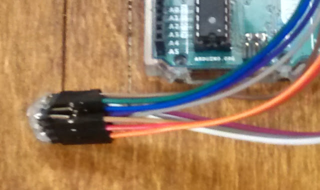
Looking at the fritzing diagram in the first post, these wires are represented by the yellow lines, which connect the channel selection of the multiplexers. Well that would explain why the knobs were interfering with each other. Twenty minutes later I'd crafted, soldered and heat-shrunk a proper loom to replace the bodge job, and with that the final problem was gone.
Conclusion.
This was a fun and challenging project which took about 2 weeks to complete, and taught me a lot about the more practical side of electronics, including not to glue things to the work bench and to replace any bodge connections with proper wiring. Unfortunately it seemed I had to learn yet again that my laziness would sooner or later bite me from behind. For future endeavours I also learned to account for how much room the wiring will take up - not just the room required for the components themselves. I'm very pleased with the result and there's not much I would change if I were to do it again. If anything I'm looking to expand on it by adding more controls sometime in the future. For now though I'll end this series with a picture of the completed controller, and a video of it in action.

Project repository on Github

Comments
Post a Comment